When it comes to intercom performance, one of the most common yet overlooked causes of installation problems is intercom cabling voltage drop. Even when equipment is correctly configured, voltage loss along cable runs can prevent devices from receiving the power to operate consistently. Installers frequently encounter issues such as indoor monitors rebooting at random, door stations failing to power up, or poor video quality.
As modern intercom systems become increasingly sophisticated, accurate voltage drop calculations are essential to system design. Understanding intercom cabling voltage drop before installation begins helps ensure stable operation and allows installers to confidently select the right cable gauge for both current requirements and future expansion.
How Voltage Drop Matters in Modern Intercom Systems
Voltage drop occurs whenever electrical current flows through a conductor. Because every cable has resistance, a portion of the supplied voltage is lost as electricity travels from the power source to the connected device.
The amount of voltage lost depends primarily on three factors: cable resistance, cable length, and current draw. As cable runs become longer or device loads increase, the resulting voltage loss becomes more significant.
Modern intercom systems are generally far more sensitive to voltage fluctuations than older audio-only systems. Video intercoms, IP-based communication platforms, integrated access control systems, and smart building devices all rely on stable operating voltages to maintain reliable performance.
Typical operating voltages include:
- 12V DC systems
- 24V DC systems
- Power over Ethernet (PoE) intercom systems
Lower-voltage systems are particularly vulnerable because even a small voltage loss can represent a significant percentage of the total supply voltage. For example, losing 2 volts in a 12V system has a much greater impact than losing the same amount in a 48V PoE network.
Excessive intercom cabling voltage drop can create numerous risks, including device instability, degraded image quality, communication errors, shortened equipment lifespan, and expensive service call callbacks.

Understanding the Variables That Affect Intercom Cabling Voltage Drop
Several factors influence the voltage loss across an intercom cable run. Understanding these variables helps installers make informed decisions about cable selection.
Cable length is often the most obvious factor. The longer the cable run, the greater the resistance and resulting voltage loss. This is why large commercial sites frequently encounter power distribution challenges.
Cable gauge also plays a critical role. Larger conductors have lower resistance and therefore produce less voltage drop. Selecting a slightly larger cable during installation can often eliminate future performance issues.
Current draw is equally important. Video monitors, access control devices, electric strikes, and relay outputs all contribute to overall system load. As current increases, voltage loss rises proportionally.
Supply voltage affects the tolerance available for voltage loss. A 24V system generally handles longer cable runs more effectively than a 12V system because the same voltage drop represents a smaller percentage of the total supply.
Environmental conditions also matter. Higher operating temperatures increase conductor resistance, further contributing to intercom cabling voltage drop.
The Basic Voltage Drop Formula Every Installer Should Know
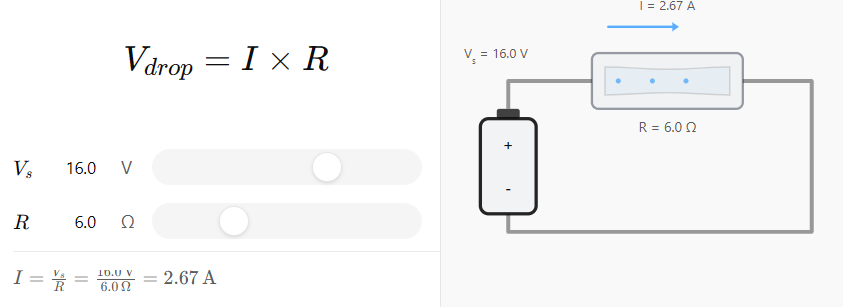
The fundamental voltage drop equation defines the relationship between:
- Vdrop = Voltage drop (volts)
- I = Current (amps)
- R = Resistance (ohms)
The calculation is straightforward. As current increases or resistance rises, voltage drop also increases: Vdrop = I x R
Resistance is determined by both conductor size and total cable length. Larger conductors have lower resistance, while longer cable runs increase overall resistance.
One common mistake is forgetting to calculate total circuit length rather than one-way distance. Electrical current travels from the power supply to the device and then returns through the circuit. This means installers must always account for the round-trip conductor length when calculating intercom cabling voltage drop.
For example:
- One-way cable distance: 150m
- Return conductor distance: 150m
- Total circuit length: 300m
Ignoring the return path can significantly underestimate voltage loss and lead to an undersized cable selection.
Step-by-Step Intercom Cabling Voltage Drop Calculations
Proper intercom cabling voltage drop calculations follow a structured process. Work through each step methodically to select suitable cable sizes for reliable long-term performance.
Step 1 – Determine Device Current Consumption
The first step is identifying the current requirements of every device connected to the circuit.
Manufacturers typically publish both normal operating current and peak current values. Installers should carefully review technical specifications rather than relying on assumptions.
Particular attention should be paid to:
- Indoor monitors
- Video door stations
- Access control modules
- Electric strikes
- Magnetic locks
- Network accessories
Startup current can be significantly higher than continuous operating current. Video monitors, especially larger touchscreen models, often draw additional power during boot-up. If only steady-state current is considered, actual voltage drop may exceed expectations during operation.
Where multiple devices share the same power circuit, all connected loads should be included in the calculation.
Step 2 – Calculate Total Cable Distance
After determining current consumption, calculate the total conductor length.
Many installers mistakenly use only the one-way cable distance. However, electrical current travels to the device and back through the return conductor.
For example:
- One-way distance = 150m
- Return distance = 150m
- Total circuit length = 300m
This round-trip measurement must always be used when calculating resistance and voltage drop.
On larger commercial sites, it is also important to account for routing pathways. Cable routes rarely follow straight-line distances. Conduit paths, risers, and cable trays often add significant length relative to the building’s physical dimensions.
Accurate measurements improve the reliability of intercom cabling voltage drop calculations and help prevent unexpected performance issues.
Step 3 – Identify Cable Resistance
Once total cable length is known, installers must determine conductor resistance.
Cable manufacturers typically publish resistance values per kilometre. These figures allow installers to calculate total resistance for a specific cable run.
Common conductor sizes include:
| Cable Size | Relative Resistance |
| 0.5 mm² | Highest |
| 0.75 mm² | Moderate |
| 1.0 mm² | Lower |
| 1.5 mm² | Lowest |
Larger conductors provide lower resistance and therefore reduce voltage loss. Where manufacturer-specific resistance data is available, it should always be used rather than relying on generic assumptions.
Step 4 – Calculate Expected Voltage Drop
With current draw and cable resistance identified, installers can calculate voltage drop.
Consider this example:
- Supply voltage = 24V DC
- Current draw = 1.0A
- Total cable resistance = 2Ω
Using the formula:
Vdrop = I × R
Vdrop = 1.0 × 2
Vdrop = 2V
This means 2 volts are lost across the cable run.
The receiving device therefore sees: 24V − 2V = 22V
This simple calculation clearly indicates whether the selected cable size is suitable for the installation.
Step 5 – Verify Remaining Operating Voltage
After calculating the voltage loss, compare the remaining voltage against the manufacturer’s requirements. Many devices specify a minimum operating voltage range. If the delivered voltage falls below this threshold, unreliable operation may occur.
For example:
- Supply voltage = 24V
- Voltage drop = 2V
- Device voltage = 22V
- Minimum requirement = 21V
In this scenario, the installation technically complies. However, the safety margin is relatively small.
Most installers prefer maintaining additional headroom to accommodate startup loads, ageing power supplies, environmental conditions, and future modifications.

Step 6 – Evaluate Future Expansion Requirements
A common mistake is designing solely for current requirements. Many intercom installations expand over time through:
- Additional indoor monitors
- Secondary gate stations
- Access control integration
- Network switches
- Auxiliary communication devices
Each new device increases overall current demand.
When calculating intercom cabling voltage drop, installers should consider future expansion capacity wherever possible. Selecting a larger cable during the initial installation is often significantly cheaper than replacing undersized wiring later.
Step 7 – Document Cable Sizing Decisions
The final step is documenting all calculations and design decisions. Installation records should include:
- Cable lengths
- Current calculations
- Selected conductor sizes
- Voltage drop results
- Future capacity allowances
Proper documentation assists future maintenance teams, simplifies troubleshooting, and supports future upgrades.
Good records also provide valuable evidence that cable sizing decisions were based on sound engineering principles rather than assumptions.
Cable Gauge Selection Guide for Long-Run Intercom Installations
The following guide provides a general starting point for cable selection. Actual sizing should always be verified through detailed intercom cabling voltage drop calculations.
| Run Length | Typical Load | Recommended Cable Size* |
| Up to 50m | Low | 0.5 mm² |
| 50–100m | Moderate | 0.75 mm² |
| 100–200m | Higher | 1.0 mm² |
| 200m+ | Heavy load | 1.5 mm² or larger |
*Actual sizing should always be confirmed through voltage drop calculations.
In many projects, upsizing conductors can be more economical than installing additional power supplies. Larger cables reduce voltage loss, provide future capacity, and simplify system architecture.
However, at very long distances, the cost of larger conductors may exceed the cost of alternative power distribution methods. Installers should evaluate both options during the design phase to determine the most cost-effective solution.

Common Installer Mistakes That Cause Voltage Drop Problems
Even experienced technicians can make mistakes when assessing intercom cabling voltage drop. Common issues include:
- Ignoring round-trip conductor length calculations.
- Using signalling cable that is unsuitable for power delivery.
- Adding devices after commissioning without recalculating load requirements.
- Mixing different cable types within the same run.
- Underestimating startup current demands.
- Assuming PoE completely eliminates voltage drop concerns.
- Failing to measure voltage under actual operating conditions.
- Selecting cable sizes based on previous projects rather than calculations.
Most voltage-related service calls can be traced back to one or more of these errors.
Read more: Hidden Infrastructure Costs in IP Intercom Tenders: Cabling, Switches & Power
When Alternative Power Distribution Methods Make More Sense
There are situations where simply increasing cable size is not the most practical solution.
Large commercial facilities, multi-building developments, industrial sites, and long driveway installations often benefit from alternative power distribution strategies.
Localised power supplies can reduce cable lengths and minimise voltage loss. Distributed power architectures place power closer to connected devices, improving efficiency and simplifying expansion.
PoE switches and midspan injectors are often effective solutions for IP intercom systems. By delivering power through structured cabling infrastructure, they can reduce the need for dedicated low-voltage power circuits.
For very large sites, fibre optic communications combined with local power supplies may provide the most reliable and scalable design approach.
The key objective remains the same: ensuring adequate operating voltage reaches every device while maintaining flexibility for future growth. In many long-distance projects, alternative distribution methods can outperform simply increasing conductor size.

FAQs
How much voltage drop is acceptable for an intercom system?
Most manufacturers recommend limiting voltage drop to a small percentage of the supply voltage while maintaining sufficient operating margin. Always verify requirements against the specific equipment specifications.
Should I use 12V or 24V for long cable runs?
Generally, 24V systems perform better over longer distances because the same voltage loss represents a smaller percentage of the total supply voltage.
How do I calculate voltage drop for multiple intercom devices?
Add the current draw of all connected devices, then use the total circuit current to calculate the voltage drop across the cable run.
Does PoE eliminate voltage drop issues?
No. PoE systems still experience voltage loss. However, higher transmission voltages and defined network standards help manage voltage drop more effectively.
What cable size should I use for a 200m intercom run?
There is no universal answer. Cable size depends on current draw, supply voltage, and equipment requirements. Installers should always perform voltage drop calculations rather than relying solely on distance guidelines.
In Conclusion
Accurate intercom cabling voltage drop calculations are essential for delivering reliable intercom installations. Whether working with video intercoms, IP-based systems, or integrated access control platforms, installers must carefully evaluate cable length, conductor resistance and future expansion requirements before selecting cable sizes.
Also, rather than treating voltage drop as a troubleshooting issue after problems arise, it should be considered a standard part of every system design. Taking the time to calculate intercom cabling voltage drop correctly from the outset ensures better performance.
Need expert advice on intercom system design, cable selection, or access control integration? Contact DHS today for professional guidance and product solutions for installers across Australia and New Zealand.