On many commercial gate projects, the biggest problems for the gate automation contractor start before they even arrive on site. That’s when the concrete has already been poured, the conduit is in the wrong position, the support posts do not suit the selected hardware, or the motor pad has been treated as an afterthought. That is where understanding cantilever gate concrete slab requirements early can save builders from rework.
Cantilever gates are more sensitive to set-out accuracy than standard tracked sliding gates because they are suspended rather than rolling along a ground track. This makes the foundation, carriage location, guide posts, run-back space, drainage and access control cabling critical. This guide is written for builders and gate installers to coordinate civil works before the concrete pour.
How Cantilever Gates Differ From Track Sliding Gates
A traditional sliding gate usually rolls on wheels over a steel track fixed to a concrete strip. The gate’s weight is supported along the track, so the concrete strip acts as a continuous running surface. This system is common, practical and cost-effective, but the track can be affected by debris, water pooling or inconsistent finished levels.
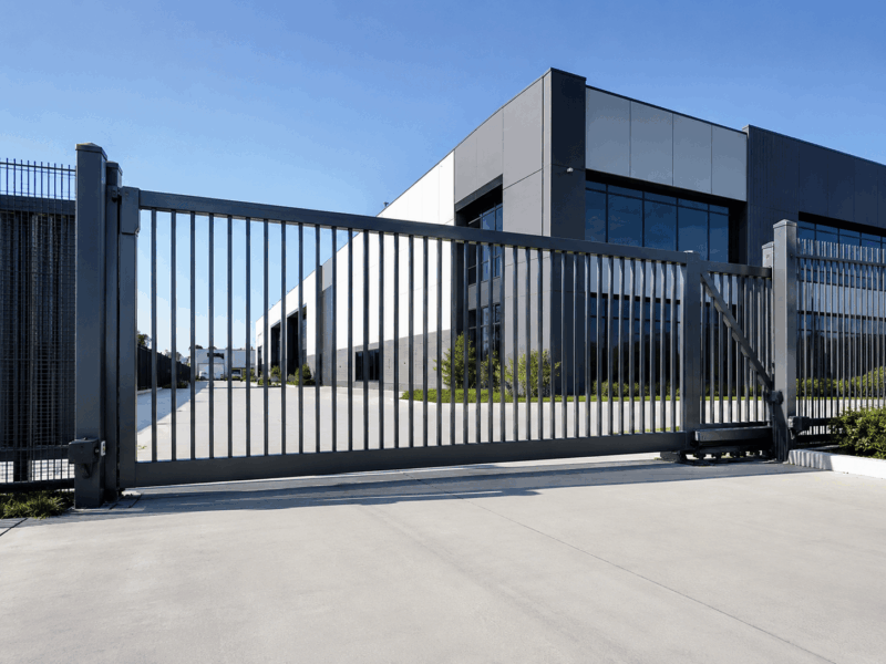
A cantilever gate works differently. Instead of rolling along a ground track, it is supported on one side by carriage assemblies, guide rollers, posts, and a counterbalance section. This allows the gate leaf to travel across the opening without a track in the driveway. Cantilever gates are often selected for gravel entries, industrial sites, sloped areas, or locations where a track would collect debris.
The important difference for builders is where the load goes. A track sliding gate needs continuous concrete support along its travel path. A cantilever gate requires stronger localised support around the carriage and post area because it is suspended from one side. The overall gate is also longer than the clear opening because the counterbalance section must sit behind the support structure. Some fitting guidance recommends an overall gate length of at least 1.5 times the clear opening, depending on the system.
Read more: Sliding Gate Vs Cantilever Gate Systems: Pros, Cons & Installation Differences
Why the Concrete Slab Matters More With Cantilever Gate Automation
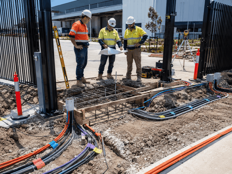
The cantilever gate concrete slab or footing is not just a place to bolt down a motor. With a cantilever gate, the foundation becomes part of the operating structure. It must support concentrated loads from the carriages, gate weight, and the forces created as the gate opens and closes.
A poorly planned cantilever gate concrete slab can create problems that appear later as “automation faults”. The gate may sag, bind, become misaligned, or place extra strain on the motor. The rack may not mesh properly with the motor pinion. Safety beams can fall out of alignment. Water may pool around electrical components.
There is no single cantilever gate concrete slab size that suits every cantilever gate. Requirements depend on the gate opening width, total gate length, finished gate weight, soil condition, traffic frequency, wind exposure, and cladding style. For commercial and industrial projects, builders should avoid relying on a generic residential footing allowance. Engineering input may be needed to operate at high cycle rates. Gate footing guidance also highlights the importance of a stable motor pad, conduit planning, drainage and sufficient concrete strength to resist vibration.
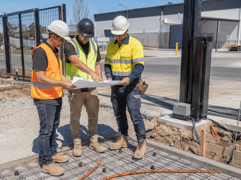
Key Information Builders Need Before Pouring Concrete
Before the concreter arrives, builders should confirm the gate system, automation requirements and access control layout. Before setting out a cantilever gate concrete slab, confirm the following information with the gate automation installer, fencing contractor and electrician:
- Gate opening width and total gate length: Do not measure only the driveway opening. Include the counterbalance section and full run-back area.
- Gate height, frame type, cladding, and finished weight: A tall, fully clad commercial gate imposes different loads than a lightweight open-frame gate.
- Support post, guide post, receiver post and end stop locations: These should be marked from the final gate design, not guessed from the fence line alone.
- Carriage or trolley model: Confirm the base plate size, carriage spacing, anchor bolt positions and required clearance around the hardware.
- Motor model and motor pad size: The motor pad must suit the selected automation unit, rack location, service access and future adjustment.
- Conduit runs: Plan conduits for motor power, control cabling, intercoms, keypads, RFID readers, safety beams, exit loops and future upgrades.
- Finished levels and site conditions: Review driveway falls, drainage paths, landscaping, kerbs, paving height and vehicle movement areas.
Overall cantilever gate length is often significantly longer than the clear opening due to the counterbalance section; some fitting guidance recommends at least 1.5 times the clear opening length, depending on the system.
Cantilever Gate Concrete Slab Requirements Builders Should Coordinate
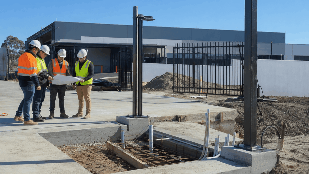
The right cantilever gate concrete slab starts with coordination. Builders do not need to become gate engineers, but they do need to ensure the slab, footings, conduits and posts are designed around the selected gate system.
The main considerations include excavation depth, reinforcement, concrete strength, curing time, anchor positioning and post support. Because cantilever gates place concentrated loads around the carriage area, the footing usually does more structural work than a simple strip used for a tracked sliding gate. The foundation must resist movement, vibration and leverage as the gate travels.
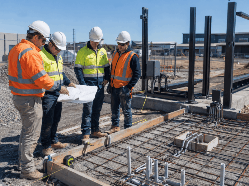
Reinforcement, base plate positions, post footings and anchor templates should be checked before the pour. Some installation guidance refers to reinforced concrete foundations, anchor bolt templates, tie rods and carriage spacing.
Moreover, the motor pad should be flat, strong, and positioned so that the motor pinion aligns correctly with the gate rack. It should not be placed too low where water can affect the motor, and it should not be too small.
For commercial sites, the safest approach is to finalise the gate hardware and automation layout before the cantilever gate concrete slab is formed.
Underground Conduits for Power, Access Control, and Safety Devices
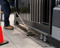
Conduit planning is one of the easiest parts of a gate project to get wrong before concrete is poured. It is also one of the messiest to fix later. Once the cantilever gate concrete slab is finished, missing or misplaced conduits may require saw cutting, core drilling, surface-mounted conduit or awkward cable routes.
Builders should coordinate early with the gate automation installer and the electrician. The motor, access control devices and safety accessories all need to be considered before the pour. Common conduit requirements include:
- Gate motor power supply: Allow for the selected power method and licensed electrical work.
- Intercom or keypad pedestal: Position conduits to suit pedestrian and vehicle approach points.
- RFID reader or access control panel: Consider reader height, user approach direction and cable route.
- Safety beams: Plan for beam locations on both sides of the opening where required.
- Vehicle exit loop or free-exit device: Coordinate loop position before driveway works are completed.
- Magnetic lock, electric lock or gate status sensor: Allow cabling if the system requires locking or monitoring.
- Spare conduit: Future upgrades are much easier when additional conduit is already in place.
Installer guidance also notes that if a sliding gate motor is hardwired, conduit may need to be set into the motor pad before concrete work is completed.
Read more: How To Connect Access Control With Your Sliding Gate System
Main Civil Works Coordination Checklist for Cantilever Gates
Good civil works coordination reduces risk for everyone involved. The following checklist focuses on the major coordination points that affect the long-term performance of a cantilever gate system.
Confirm the Gate System Before the Slab Is Designed
The selected gate hardware should drive the slab design. Meanwhile, carriage spacing, base plate footprint, guide post position, counterbalance length, rack position and motor location can all vary depending on the system. Before the concrete design is finalised, confirm the actual cantilever hardware, gate weight, motor model and access control layout.
Mark the Full Gate Travel and Counterbalance Zone
Builders should not mark only the clear driveway opening. The gate must have enough run-back space to fully open, including the counterbalance section behind the carriage area.
This zone should be checked, and if the gate cannot travel freely, the automation system may be forced into awkward positioning, or the opening may be reduced. A practical cantilever gate concrete slab set-out should account for the full movement of the gate, not just the visible driveway gap.
Coordinate Post Footings With Fencing and Gate Hardware
Support posts, guide posts, receiver posts and end stops should be set out with the gate installer. Post placement affects alignment, closing accuracy, safety device positioning and hardware performance.
If posts are installed too early without reference to the selected carriage and guide system, they may need to be moved, modified or packed out. On commercial sites, this can affect fencing lines, finished surfaces, and gate clearances.
Allow for Drainage and Finished Surface Levels
The cantilever gate concrete slab should not create a low point around the motor, carriage hardware, or conduit exits. Water pooling around automation equipment can shorten component life and increase maintenance problems. Finished levels should allow the gate to move freely while protecting electrical and mechanical components from water, mud, gravel, and debris.
Keep Conduits Accessible but Protected
Conduits should emerge where the equipment will be installed, but they should not interfere with base plates, anchor bolts, posts, pedestrian movement or vehicle paths.
For a commercial gate, it is worth allowing spare conduit for future additions such as RFID readers, intercom upgrades, vehicle detection, CCTV integration, lighting or building automation connections.
Check Curing and Handover Timing
Gate installation should not be scheduled before the concrete has sufficiently cured for loading, drilling, or anchoring. Cantilever hardware can place significant forces on the footing, especially around the carriage area.
Some installation guidance recommends allowing the concrete pad to cure before fixing cantilever carriages. Builders should confirm the curing time, site access, handover sequence, and responsibility for the final set-out before booking the automation installation.
Common Mistakes That Cause Rework on Cantilever Gate Projects
The issue is usually not poor workmanship by one trade, but a lack of coordination between civil works, fencing, electrical, access control and automation. Common mistakes include:
- Pouring concrete before final hardware selection: The slab may not suit the carriage spacing, base plates or motor location.
- Allowing only for the driveway opening: The counterbalance section and run-back area are forgotten.
- Placing conduits in the wrong spot: Conduits may clash with the motor, posts, base plates or anchor bolts.
- Making the motor pad too small: The motor fits, but there is no room for servicing, adjustment or cover removal.
- Forgetting access control conduits: Intercoms, card readers, keypads and safety devices become difficult to cable neatly.
- Setting posts too early: Guide rollers, receiver posts and end stops may not align with the final gate system.
- Ignoring drainage and finished paving height: Water, debris or level changes can affect long-term automation performance.
- Treating a commercial gate like a residential gate: Heavier gates, higher cycles and wider openings need more planning.
- Not leaving spare conduit: Future upgrades become more expensive and disruptive.
A well-planned cantilever gate concrete slab gives the automation installer a reliable base to work from and reduces the chance of late-stage site compromises.
When Builders Should Involve the Gate Automation Installer
The best time to involve the gate automation installer is before the cantilever gate concrete slab is finalised. Early input can help builders confirm the motor position, carriage support area, access control locations, safety beam placement and service clearance before concrete works begin.
This is especially important on commercial sites, where the gate may need to integrate with broader smart-building security systems. A gate that works mechanically but was not planned for access control can still create expensive installation issues later.
DHS can support builders with gate automation hardware, product selection, installer coordination, access control planning and technical guidance across smart commercial entry projects. Contact us today to reduce last-minute changes and deliver a cleaner result for the client.
FAQs
Do cantilever gates need a concrete slab across the whole driveway?
Not usually in the same way as track sliding gates. Cantilever gates do not rely on a ground track across the driveway, but they do require strong support around the carriage, post, and motor areas.
Can builders pour the slab before choosing the gate motor?
It is not recommended. The motor footprint, rack location, conduit exit, and service clearance should be confirmed before the pour.
Where should the underground conduit come up for a cantilever gate?
Conduits should emerge near the motor, access control devices, safety beams, and any required control equipment. The exact position should be confirmed with the installer before concrete works.
Do commercial cantilever gates need engineered footings?
Often, yes. Heavy gates, wide openings, poor soil, wind exposure, and high-cycle commercial use may require engineering input.
What is the biggest pre-pour mistake builders make?
The most common issue is pouring concrete before confirming gate hardware, carriage positions, motor location, and conduit routes.