
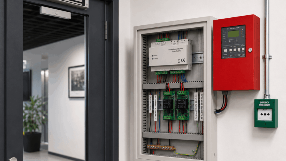
A magnetic security door should operate perfectly during normal access-control testing. At the same time, the installer must also prove that the same door will unlock immediately when the fire alarm interface changes state.
This is where fire alarm access control relay wiring becomes critical. The interface allows the fire detection system to override normal access-control operation and remove locking power during an emergency condition.
This article focuses on magnetic security doors using fail-safe locking arrangements. Successful integration involves more than connecting two relay terminals. Installers must understand contact states, dry contacts, power-supply behaviour, emergency release devices, controller dependencies and the responsibilities of the fire-alarm contractor.
How a Fire Alarm Interface Changes the Magnetic Lock Circuit
This is what the fire alarm interface is expected to achieve: a magnetic lock remains secure only while electrical power is continuously applied; when that power is removed, the lock releases.
In a properly designed arrangement, the fire alarm interface either interrupts the lock’s power path directly or commands an approved release circuit when the fire system enters an alarm state.
A simplified signal sequence may look like this:
Fire alarm control panel → interface relay → access-control or lock-power circuit → magnetic lock releases
There are several ways this sequence may be implemented.
In a controller-input arrangement, the fire alarm relay sends a status signal to an input on the access controller. The controller then activates programmed door outputs to unlock selected doors.
In a direct interruption arrangement, the fire alarm relay physically opens the magnetic-lock power circuit to remove power without depending on a software command from the access controller.
A combined system may use both methods. The controller receives the fire alarm status for monitoring and event reporting, while a separate hardwired circuit removes power from the magnetic lock.
The output by the fire system is often a dry contact, also called a voltage-free contact, in which the relay changes electrical continuity between its terminals but does not necessarily supply voltage. Fire panel terminals should never provide a powered output.
The final wiring method should follow the approved project design, applicable workplace emergency exit requirements, and coordination with the fire-system provider rather than being improvised during access-control commissioning.
Read more: Magnetic Lock Holding Force: Selecting 300kg vs. 600kg for Secure Enclosures

Normally Open, Normally Closed and Common Relay Contacts
This section will help you understand relay contact terminology before making any connection. The labels COM, NC and NO describe how the internal relay contact behaves, but they do not automatically reveal the complete fire-system logic. Here are their functions in the interface:
- Common, or COM – The moving contact shared by the selected circuit
- Normally closed, or NC – Connected to COM while the relay is in its normal state
- Normally open, or NO – Connected to COM after the relay changes state
The word “normal” refers to the relay’s resting or non-energised condition. However, some fire-alarm interfaces are energised during normal operation. In these arrangements, the relay may change state when an alarm occurs, when power is lost or when an interface fault develops.
For this reason, terminal labels alone do not prove how the door will behave under every condition.
Many magnetic-lock release circuits use the COM and NC contacts in series with the positive lock-power conductor. During normal operation, continuity between COM and NC allows power to reach the lock. When the relay activates, the NC contact opens, interrupting the circuit and releasing the door.
Other systems deliberately energise the interface relay under normal conditions. This approach may allow a loss of fire-panel power or interface control to create a release or fault response, depending on the approved design.
Before connecting the access-control circuit, it is important to confirm the relay operation using the fire contractor’s documentation and a suitable multimeter. Check continuity in the normal state, alarm state and any relevant power-failure condition.
Never select a contact based only on an assumption that NC automatically means “safe” or NO automatically means “alarm”. The complete circuit behaviour must be verified.
Breaking Down the Fire Alarm Access Control Relay Wiring Path
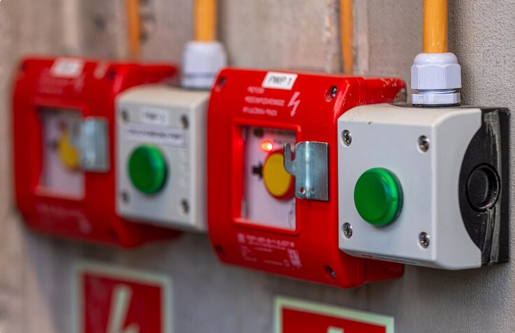
A clear understanding of the locking-power path makes installation and fault-finding much easier. The following simplified diagram shows one conceptual arrangement for fire alarm access control relay wiring on a fail-safe magnetic lock.
This is the typical conceptual wiring path:
Lock power supply positive -> Fire relay COM -> Fire relay NC -> Emergency door release device -> Access-control lock relay -> Magnetic lock positive -> Lock power supply negative -> Magnetic lock negative
This is a conceptual signal path rather than a universal wiring drawing. Terminal numbers, device order, monitoring requirements and cable arrangements vary between products and project designs.
Lock Power Supply
The magnetic lock must receive the correct regulated voltage and sufficient current from an access control power supply. Common lock voltages include 12 V DC and 24 V DC, depending on the specific device’s requirements.
The power supply should also have enough capacity for the magnetic lock, controller, readers, relays and other connected equipment. Allowance may be required for startup conditions, multiple doors and battery charging.
In a direct-release arrangement, the fire relay is inserted into the locking-power path. In other systems, the fire relay operates a separate isolation or interposing relay that interrupts the lock circuit.
Fire Alarm Interface Relay
The interface relay provides the state change that initiates the emergency release. In a common arrangement, lock-power positive enters the COM terminal and leaves through NC.
During normal operation, the COM-to-NC path remains closed, allowing current to continue towards the magnetic lock. When the fire alarm condition changes the relay state, the NC contact opens, interrupting the positive conductor.
Emergency Door Release Device
A local emergency door release unit may be installed in series with the lock supply so that activating it directly removes power from the magnetic lock. This device should not depend entirely on the access-control controller, network or software. Its purpose is to provide a local release method for emergency operations.
The exact type and placement of the device should follow the approved door design and project requirements.

Access-Control Lock Relay
During everyday operation, the access controller switches the door in response to authorised card reads, keypads, mobile credentials, intercom release commands, request-to-exit devices or programmed schedules.
The controller may interrupt lock power directly through its onboard relay, or it may operate an external relay or power-supply input.
The fire alarm override must remain capable of releasing the magnetic lock even if the controller freezes, loses network communication or fails to process a programmed input. This is one reason project designers may specify a separate hardwired interruption path.
Magnetic Lock
A fail-safe magnetic lock releases when electrical power is removed. However, installers should not assume that opening a relay contact will always result in an immediate release.
Check whether another power source, a secondary output, or a parallel connection continues to energise the lock. Delayed power-supply outputs, capacitive energy, incorrect suppression devices or auxiliary control equipment may also affect release timing.
Measure the voltage directly at the lock under normal conditions and during the simulated fire condition. The voltage should fall as required by the system design, and the door should release without a credential or software command.
Direct Lock-Power Interruption
With direct interruption, the fire relay physically opens the lock-power circuit. This provides a clear electrical release path but requires the fire relay contacts to be suitable for the connected voltage, current and load characteristics.
Do not route full magnetic-lock current through the fire relay unless its contact rating has been checked and the arrangement is approved.
Interposing Relay Arrangement
An interposing relay provides electrical separation between the fire system and the access-control load.
The fire panel changes the state of its own dry contact, which operates a separate relay. The interposing relay then switches the magnetic-lock circuit using contacts rated for the required load.
This approach can protect the fire-system interface from carrying lock current and may simplify electrical isolation. However, the relay coil voltage, contact rating, normal state, fault behaviour and power source must all be correctly selected.
Before starting installation, obtain a project-specific fire alarm access control relay wiring diagram showing terminal numbers, cable cores, power-supply locations, controlled doors and contractor responsibilities.

Controller Input Only vs Hardwired Lock-Power Release
There is no single interface method suitable for every project. The correct arrangement depends on the door function, the approved system design, the equipment capabilities, and the required monitoring.
| Method | How it works | Main consideration |
| Controller input | The fire relay tells the access controller to unlock selected doors | Depends on controller power, programming and output operation |
| Hardwired interruption | A fire relay or interposing relay physically removes maglock power | Requires correct contact and load design |
| Combined interface | The controller records the event while a hardwired path releases the lock | Provides event visibility and independent release logic |
A controller-input-only arrangement can provide flexible programming. One fire input may release selected doors, generate alarms, change schedules and record events.
However, this method introduces additional dependencies. The controller must remain powered, the input must be correctly programmed, the appropriate door outputs must operate, and the software configuration must remain intact. A controller, network, output or programming failure could prevent the release command from reaching the intended door.
A hardwired interruption reduces reliance on access-control logic by physically removing power to the magnetic lock. It still requires appropriate contact ratings, cable routing, fault management and coordination with local emergency release devices.
The combined approach is often useful where the project requires both independent physical release and access-control event reporting. The hardwired circuit releases the lock, while the controller input records the alarm condition and helps operators identify which doors are affected.
The selected method should be documented rather than left for the installer to determine at the end of the project.
Installation Errors That Cause Maglocks to Remain Energised
A magnetic lock that stays energised during a simulated alarm usually indicates a problem in the power path, relay logic, or system programming.
One common mistake is using NO contacts when the approved circuit requires NC contacts, or vice versa. Installers may also misunderstand the relay’s true normal state, particularly when the fire interface is energised during normal operation.
Another frequent problem occurs when the fire relay is connected only to a controller input, but the required door-release response has not been programmed. The controller may display the input change while the lock output remains active.
Other faults include bypassing the local emergency release device, interrupting the wrong conductor, switching the wrong power-supply output or leaving a secondary feed connected to the lock.
The following points should be checked during pre-commissioning:
- Confirm the correct COM, NC and NO terminals.
- Verify the relay state during normal, alarm and power-loss conditions.
- Check that the fire input is mapped to the correct doors.
- Confirm the emergency release device interrupts the lock power.
- Check the relay contact rating against the connected lock load.
- Look for parallel or secondary power feeds.
- Keep dry contacts separate from powered outputs.
- Verify that shared power circuits do not release unintended doors.
- Test the system while operating from battery backup.
Read more: Smart Lock Failure Scenarios and Emergency Override Options

Plan Fire Alarm and Magnetic Lock Integration with DHS
Reliable fire alarm access control relay wiring requires clear design coordination between the access-control installer, fire-alarm contractor, electrician, builder and project representative. Every relay state, power source and release device should have a documented purpose.
Digital Home Systems can assist installers, builders and security integrators with compatible magnetic locks, access-control panels, interposing relays, emergency release devices and regulated power supplies. Our team can also support hardware selection and system planning for integrated gate and door solutions across commercial, residential and accessibility-focused projects.
Contact us today to discuss more about your next magnetic security door system!
Frequently Asked Questions
Does a magnetic lock unlock when power is removed?
Generally, a fail-safe magnetic lock releases when its power supply is interrupted. Installers should still verify the complete circuit because secondary feeds, delayed outputs or incorrect wiring may keep the lock energised.
Can the fire alarm relay connect directly to the maglock?
It may be possible in some designs, but only when the relay arrangement and contact rating are suitable. An interposing relay may be required to isolate systems or switch a higher electrical load.
Should the fire relay connect to NO or NC?
The correct contact depends on the approved system logic and the relay’s normal operating state. Installers should verify the expected behaviour during alarm, normal operation, power failure and cable faults.
Is an access-controller unlock command enough?
A controller input may release doors through software, but it introduces dependence on controller power, programming and functioning outputs. Some projects use an independent hardwired power-release path.
Who should commission the fire alarm and access-control interface?
Commissioning should be coordinated between the access-control installer, fire-alarm contractor and other responsible project parties. Each contractor should verify the part of the interface within their scope.