
A gate operator that looks suitable on paper can still struggle once a site becomes busy. The gate may sit well below the motor’s maximum weight rating, yet the operator slows down or pauses on thermal protection. The issue is often not total daily traffic. A site may process only a few hundred vehicles per day but demand rapid opening and closing movements within a concentrated 20- or 30-minute period. That short burst can create far more thermal and mechanical stress than steady, low-frequency use.
Calculating the automatic gate motor duty cycle helps installers match the operator to the real traffic pattern. The assessment should consider peak arrivals and departures, ambient temperature, actual mechanical load, and other factors. Let’s learn more!
What an Automatic Gate Motor Duty Cycle Actually Measures
What does the rating describe? Duty cycle is the proportion of an operating period during which the motor is actively running.
Duty cycle (%) = motor running time ÷ total elapsed time × 100
For example, if a motor runs for 18 minutes in an hour, the calculated duty cycle is 30%. That does not mean every operator labelled 30% will suit the site, because manufacturers may express operating capacity in different ways.
| Rating format | What installers should check |
| Percentage duty cycle | Maximum proportion of time the motor may run |
| Cycles per hour | Maximum complete cycles allowed within one hour |
| Consecutive cycles | Maximum cycles before a recovery period |
| Intensive or continuous use | Manufacturer-defined operating class and conditions |
A complete gate cycle normally includes one opening movement and one closing movement. However, product documentation may define a “cycle”, “manoeuvre” or “operation” differently, so always confirm the wording in the specific manual.
The open-hold delay is usually not motor running time because the gate is stationary. It still affects throughput, recovery time and the number of cycles requested during the peak period.
Do not assume that a rating of 30 cycles per hour allows all 30 cycles to occur back-to-back. Some manufacturers publish a separate consecutive-cycle limit and reduce the allowable cycles based on gate length or weight. Nice documentation, for example, specifies hourly and consecutive limits with further reductions as gate dimensions and load increase.
Build a Peak-Traffic Profile Before Calculating Motor Capacity
A reliable automatic gate motor duty cycle calculation starts with traffic information from the busiest realistic window, not an average daily estimate. This matters for apartment buildings, offices, schools, warehouses and industrial sites.
Before selecting an operator, gather the essential information as below:
- Vehicles entering and exiting during the busiest 15, 30 and 60 minutes
- Whether entry and exit share one gate
- Average vehicles passing during each opening
- Gate opening and closing travel times
- Auto-close delay, loop logic and access-control sequence
- Queue behaviour and tailgating controls
- Shift changes, school pickup periods and delivery windows
- Seasonal, tenant or event-related traffic increases
Next, separate vehicle movements from gate cycles, as ten vehicles do not always create ten complete cycles. A loop-controlled entrance may hold the gate open while several authorised vehicles pass, while a higher-security site may require the gate to close behind every vehicle. Therefore, use the intended operating logic rather than automatically assigning one full cycle to every vehicle. For instance:
| Peak period | Vehicles | Average vehicles per opening | Required gate cycles |
| Morning entry | 60 | 1.2 | 50 |
| Evening exit | 45 | 1.5 | 30 |
How to Calculate the Automatic Gate Motor Duty Cycle
Once the traffic profile is documented, it’s time to complete the calculation in four practical steps. Each step should reflect realistic site behaviour rather than optimistic assumptions.
Calculate the Required Number of Gate Cycles
Required cycles = vehicle movements ÷ average vehicles passing per opening
Round the result up. If separate gates manage entry and exit, calculate them independently. If one gate handles both directions, combine the realistic demand and include visitors, deliveries, remote releases and failed access attempts that may trigger extra movements.
For 60 vehicles passing at an average of 1.2 vehicles per opening: 60 ÷ 1.2 = 50 full cycles
Access-control and loop logic can therefore change the required automatic gate motor duty cycle without changing the number of vehicles using the site.
Measure the Motor Run Time per Full Cycle
Motor run time per cycle = opening run time + closing run time
Measure the gate on site where practical, or use the manufacturer’s operating time for the proposed geometry and travel distance. Include powered leaf delays or lock-release sequences that extend an individual operator’s running time.
For a double swing gate, do not add both operators’ run times simply because two motors are installed. When both leaves move simultaneously, assess each motor according to how long it runs and the load it carries.
Convert Cycle Demand into a Percentage
Required duty cycle (%) = cycles per hour × motor run time per cycle ÷ 3,600 × 100
Consider this worked example:
- Peak demand: 60 vehicles in 30 minutes
- Average vehicles per opening: 1.2
- Required cycles in the peak period: 50
- Equivalent hourly demand: 100 cycles per hour
- Opening time: 12 seconds
- Closing time: 12 seconds
- Motor run time per cycle: 24 seconds
100 × 24 ÷ 3,600 × 100 = 66.7% required duty cycle
An operator rated for 25% or 30% duty would be unsuitable for this pattern, even if its maximum gate weight exceeds the actual gate weight. Manufacturer catalogues show that operators may be rated by percentage, cycles per hour or intensive-use classifications, so the operating rating must be checked separately from gate weight.
The result represents active motor demand across the assessment period. Compare it with the exact manual, including the manufacturer’s cycle definition and any restriction on consecutive operation.
Check the Concentrated Burst, Not Only the Hourly Average
An hourly figure can hide a damaging short-term queue. Therefore, it is necessary to run a second test for the busiest 5-, 10-, or 15-minute period.
Suppose an entrance requires 20 full cycles in ten minutes, but the shortlisted operator allows only 15 consecutive cycles. The hourly average may look acceptable, yet the queue exceeds the operator’s short-term limit before adequate recovery time is available.
Compare the site requirement against:
- Percentage duty cycle
- Maximum cycles per hour
- Maximum consecutive cycles
- Maximum continuous run time
- Ambient-temperature limits
- Gate length and weight derating
- Battery or solar operating limits
Even “continuous duty” should not be treated as unlimited. The manufacturer’s definition, permissible load, temperature range, safety settings and installation conditions still apply. Industrial operators may be marketed as continuous-duty, while other commercial products specify fixed hourly and daily limits.
Derate the Calculation for Real Gate and Site Conditions
The traffic calculation describes the required demand, but it does not prove the physical gate can achieve it. The automatic gate motor duty cycle must be considered together with current draw, mechanical resistance and heat generation.
A gate that is difficult to move manually forces the motor to work harder on every cycle. Common causes include worn wheels, damaged track, poor guide alignment, stiff hinges, incorrect operator geometry, solid infill exposed to wind, excessive rack pressure and long travel distances.
Electrical and control conditions can also add stress. Voltage drop, undersized power supplies, weak batteries, frequent reversals, aggressive acceleration settings and electric locks may affect performance. High ambient temperatures can also reduce operating margin. Some control systems limit operation based on motor load, cycle duration, and temperature to reduce the risk of overheating.
Before final specification, carefully check the following factors:
- Manual gate resistance with the operator released
- Wheel, track, hinge and guide condition
- Operator geometry and mounting dimensions
- Gate mass, leaf length and wind exposure
- Cable size, supply voltage and voltage drop
- Expected summer temperature at the enclosure
- Battery condition and backup requirements
- Future traffic growth and maintenance quality
There is no universal safety margin for every project. Headroom should reflect the manufacturer’s derating tables, measured resistance, environmental conditions, traffic uncertainty and expected future demand.
One official sliding-gate manual shows permitted hourly and consecutive cycles reducing as the leaf becomes longer, with heavier leaves applying a further percentage reduction. Repair or realign a mechanically poor gate rather than trying to compensate with an unnecessarily oversized motor.
Read more: Motor Torque Calculations for Sliding Gate Automation
Match the Calculated Demand to the Correct Operator Class
After calculating the required automatic gate motor duty cycle, you can compare shortlisted operators under equivalent conditions to choose the best one. Remember that maximum gate weight is only one part of the decision.
Low-frequency entrances can be operated by a residential or light-duty operator. Apartment and shared-access sites usually need a high-cycle residential operator, while office and industrial entrances are better suited to commercial systems. For near-continuous vehicle traffic, a continuous-duty operator or boom gates may be the more practical option.
Additionally, motor voltage alone does not establish suitability. Many 24V DC products are designed for frequent operation, but installers must still use the published cycle, load and temperature ratings. Current Nice Robus data, for example, lists 24V DC models with specific cycles-per-hour ratings for a four-metre leaf.
Also compare electromechanical and hydraulic designs, battery-dependent and mains-powered systems, single-phase and three-phase equipment, and operators intended for sliding gates, swing gates or barriers.
A faster operator can reduce active runtime and improve throughput, but speed must remain compatible with gate mass, controller settings, force limits, safety devices, and the site risk assessment.
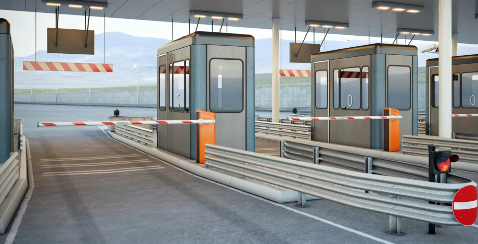
For very high vehicle flow, a boom barrier may be more suitable than repeatedly cycling a large sliding or swing gate. Depending on the security plan, the main gate may remain open during a supervised peak period while the barrier manages individual vehicles.
Read more: The Estimator’s Checklist: Specifying Commercial Gate Motors Without Underquoting
Document the Assumptions Before Ordering
Record all data, including the traffic window, vehicles per opening, cycle definition, measured travel time, gate resistance, derating factors and manufacturer limits used in the automatic gate motor duty cycle assessment. This helps the estimator and installer understand why a particular operator was selected for their automatic gate installation. It also reduces disputes if access-control logic changes or the site later processes more vehicles than originally advised.
During commissioning, it is also important to confirm actual travel times, observe queue behaviour, test all safety devices and check that the gate moves freely. Where the controller provides cycle counters, fault history, temperature alarms, or motor current diagnostics, we also need to record a baseline for future maintenance.
Choose Gate Automation Hardware with Proper Operating Headroom
Correct automatic gate motor duty cycle sizing reduces overheating and avoidable wear. More importantly, it helps the entrance operate reliably during shift changes or morning arrivals. In addition, it is vital to calculate the required cycles, measure motor runtime, test concentrated bursts, assess gate resistance, and apply the manufacturer’s exact limits. Avoid choosing equipment solely from maximum gate weight or motor voltage.
Digital Home Systems works with installers, electricians, builders and integrators to specify gate automation systems for real project conditions. Contact us today to match an operator to your gate size, traffic profile, and peak-use requirements.
Frequently Asked Questions About Gate Motor Duty Cycles
Is a 100% duty-cycle gate motor the same as continuous duty?
Not automatically. It is always recommended to check the manufacturer’s definition, temperature limits, maximum consecutive operating time, gate load, and recovery requirements.
Does the gate’s open-hold time count as motor running time?
Usually not, because the motor is stationary. It still affects throughput, spacing between powered movements, and the number of cycles demanded.
Do I count both motors on a double swing gate?
Assess each motor based on its individual runtime and load. Do not double the duty percentage simply because two operators move together.
Can a faster motor reduce the required duty cycle?
Potentially. Shorter travel times reduce active motor runtime, but speed must remain suitable for the gate, safety system, force settings, and manufacturer limits.
Should daily vehicle numbers be used for motor selection?
Daily totals help with lifecycle planning, but peak 15-, 30-, and 60-minute demand is more important for sizing. A modest daily total can still include a severe short-term burst.