PE beams can look correctly aligned during commissioning, with normal indicator LEDs and a gate or door operator passing basic tests. But on-site, installers may still encounter random stops, false safety triggers, or intermittent lockouts.
In this case, reliable photoelectric beam sensor alignment is not just about pointing the transmitter and receiver at each other; it also depends on signal margin, mounting stability, reflections, sunlight angle, beam height, cable condition, and how shadows move across the detection path.
For installers working on commercial gates, understanding these site conditions can save repeat callouts and unnecessary part replacement.
Why PE Beams Trigger Incorrectly Even After Basic Alignment
A photoelectric beam can pass a quick commissioning test but still fail once the site is operating normally. Basic photoelectric beam sensor alignment proves that the transmitter and receiver can see each other at that exact moment. It does not always prove that the system has sufficient tolerance to sunlight, vibration, moving shadows, wet surfaces, vehicles, or reflective backgrounds.
This is why false triggers often appear random. The beam may work perfectly during installation, then cause problems when the sun is low, after rain when the concrete becomes reflective, or when a sliding gate vibrates as it closes.
Common causes of PE beams triggering incorrectly include:
- Marginal optical photoelectric beam sensor alignment with low signal reserve
- Sunlight entering the receiver at certain times of day
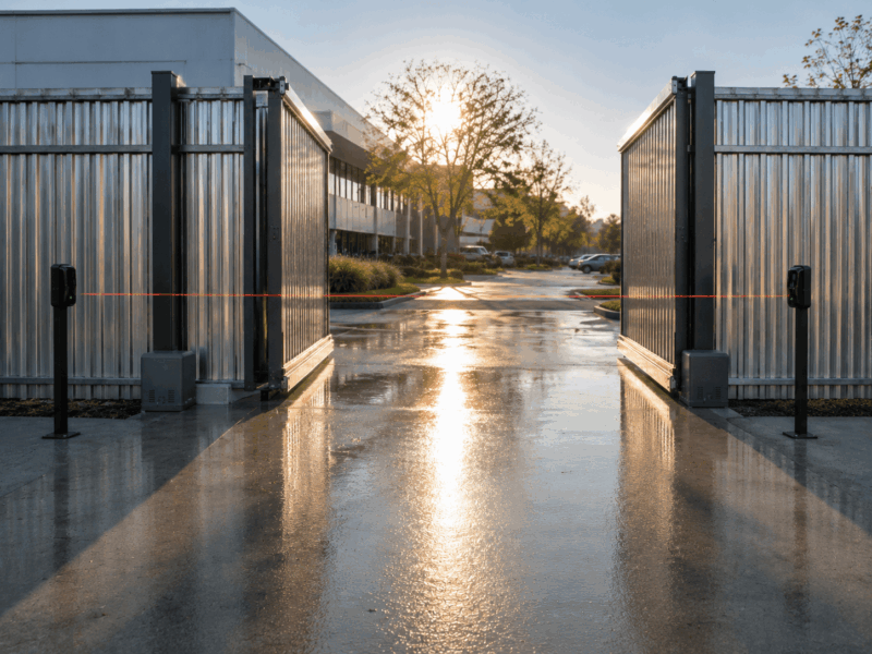
- Reflection from polished gates, stainless posts, glass, mirrors, wet concrete or vehicle panels
- Shadows from trees, fences, signage, pedestrians or moving gates
- Mounting brackets vibrating under gate movement
- Dirty lenses or condensation reducing the received signal
- Beam height or angle creating partial obstructions
- Incorrect sensitivity settings or poor range adjustment
Some newer smart sensors include alignment aids, signal indicators, or diagnostic LEDs that help indicate detection quality, contamination, vibration, or a weakening signal before full failure occurs. These features are useful, but they do not replace careful installation practice. Good photoelectric beam sensor alignment still depends on understanding how the sensor behaves in the actual site environment.
Related: The W16 and W26 product families a new generation of SICK photoelectric sensors
Shadow Triggers: Diagnosing Moving Light Patterns Across the Beam Path
Shadow-related faults are often misdiagnosed as PE beam faults. The issue may appear only at certain times of day, such as early morning or late afternoon, or during windy weather. On commercial sites, shadows can also be created by fencing, gate leaves, vehicles and nearby buildings.
In most cases, shadows do not “block” the beam in the same way as a person, vehicle or solid obstruction. However, changing light patterns can reduce contrast and interfere with the receiver. A beam that is only just aligned may become unstable when light and shade move across the receiver.
Before replacing the sensor, installers should inspect how the site behaves when the fault actually occurs. A test at midday may not reveal a problem that happens at 7:30 am.
Practical installer checks include:
- Revisit the site when the client reports the problem.
- Observe whether the beam path crosses moving tree, gate or fence shadows.
- Check whether the receiver faces direct low-angle sun.
- Watch the sensor indicators while shadows move across the path.
- Test with the gate fully open, halfway open and fully closed.
- Inspect whether moving gate leaves briefly cross or reflect into the beam path.
- Check whether nearby vehicles, glass or metal surfaces affect the receiver.
DHS works with installers on difficult access control and gate & door automation solutions. In many cases, the best result comes from diagnosing the whole entry system, including beam location, gate movement, mounting surface, control inputs and surrounding site conditions.

Fine-Tuning Photoelectric Beam Sensor Alignment for Reflection-Prone Sites
Reflection issues are especially common around commercial entrances. PE beams are often installed near aluminium fencing, glass doors, vehicle panels, wet driveways, roller shutters and metal gate frames. These surfaces can reflect light in unexpected directions, causing the receiver to behave unpredictably.
For installers, the key is to confirm that the receiver is seeing the intended beam path, not a reflected or unstable path. This is where photoelectric beam sensor alignment becomes more than a simple left-right adjustment.
Step 1: Confirm the Sensor Type
Start by confirming the type of photoelectric sensor being used. Through-beam sensors use a separate transmitter and receiver. Retro-reflective sensors send light to a reflector and receive the returned signal. Diffuse reflective sensors rely on light reflected from the target object itself.
This matters because each type reacts differently to shiny surfaces and stray light. A through-beam setup is usually more reliable across longer gate openings, but the receiver still needs a clean line of sight. Retro-reflective sensors can be affected by reflector position, angle and background reflection.
Step 2: Check Whether the Receiver Is Seeing the Real Beam
A sensor can appear aligned even when receiving light reflected from a nearby surface. This can happen near stainless steel posts, glass panels, glossy gate frames or wet concrete. The system may pass a basic obstruction test, but the signal can become unstable when a vehicle, a shadow, or a moving gate changes the reflection path.
Slightly adjust the receiver angle and observe whether the signal remains stable or drops suddenly. If a tiny movement causes a major change in the signal, the setup may have poor signal reserve or be relying on a reflected path.
Step 3: Adjust Angle, Not Just Height
When troubleshooting reflections, installers often adjust beam height but forget about the angle. In many cases, a small angular change is more effective than moving the sensor higher or lower.
Avoid mounting the beam perfectly parallel to large reflective surfaces where possible. A slight offset can reduce specular reflection and help the receiver focus on the intended transmitter path.
Step 4: Confirm Stable Signal Margin
One successful obstruction test is not enough. A reliable PE beam should have enough signal margin to remain stable as site conditions change. This is especially important along long commercial driveways, at exposed sliding gates, and at external pedestrian access points.
Where available, check diagnostic LEDs, signal strength displays or amplifier values. Sensor manufacturers often highlight the value of visualising received light intensity when subtle light differences are involved. This helps installers choose settings based on the actual received signal, not guesswork.
Step 5: Shield the Receiver From Stray Light
Ambient light entering the receiver sometimes looks like reflection instability. Low-angle sun, vehicle headlights or light bouncing from glass can interfere with detection quality.
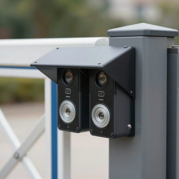
Where appropriate, use manufacturer-approved hoods, shields or mounting accessories. Do not create improvised covers that trap water or block ventilation. If shielding is not enough, reposition the receiver or change the angle so it is less exposed to direct light.
Also check cable entry points and seals. Water ingress, condensation and dirty lenses can reduce signal strength and make the receiver more vulnerable to stray light.
Step 6: Re-Test Under Real Operating Movement
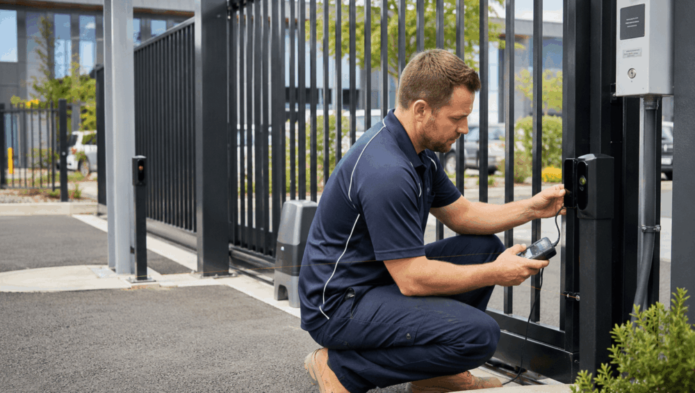
After adjustment, test the system under real operating conditions. Run the gate or door through full cycles. Test while vehicles pass through, while pedestrians use the entrance and while the gate is in different positions.
If the issue happens after rain, wet the surrounding pavement and check whether reflections change. If the issue happens in bright sunlight, return at the relevant time of day where possible. If the site has polished metal or glass nearby, observe how the receiver behaves as the angle of the light changes.
Good photoelectric beam sensor alignment is about creating a stable beam path with sufficient tolerance for real-site conditions, not just achieving temporary LED confirmation during installation.
Mounting Stability: The Overlooked Cause of Intermittent Beam Faults
Even when the optical setup is correct, poor mounting can create intermittent faults. Vibration can pull sensors out of photoelectric beam sensor alignment, especially on long sliding gates, swing gate posts, exposed perimeter fencing, and lightweight mounting posts.
This problem is common when beams are treated as a final accessory rather than as part of the main entry system. A sensor may be aligned perfectly during commissioning, then shift slightly each time the gate closes, the post flexes or the wind loads the structure.
Common installation mistakes include:
- Beams fixed to flexible fencing instead of stable posts
- Brackets mounted too close to vibrating gate hardware
- Sensor housings were not tightened properly after adjustment
- Posts moving in soft ground or cracked concrete
- Cable tension pulling the sensor body out of position
- Gate impact or wind loading affecting the beam path
Optical-axis alignment becomes harder over longer distances, and small movements can have a bigger effect. For this reason, installers should check mounting stability as part of every photoelectric beam sensor alignment process.
Site Conditions That Make PE Beam Alignment More Difficult
Some sites are naturally harder to stabilise than others. A short, sheltered pedestrian gate may be simple to commission, while a wide commercial sliding gate may require more careful planning.
Long driveways and wide commercial gate openings increase the importance of accurate photoelectric beam sensor alignment and stable mounting. Highly reflective aluminium, stainless finishes, and wet pavement can all increase the risk of stray light or reflection. Direct east-west sun exposure can also create issues at specific times of the day.
Other difficult conditions include dust, spider webs, insects, landscaping near the lens, multiple sensors installed close together, sloped driveways, uneven ground and vehicle headlights hitting the receiver at night.
Installers should document these conditions during commissioning. A false trigger may not appear during the first test, so photos and notes can be valuable for future service calls. Record the beam position, bracket fixing, cable entry, reflector position, surrounding reflective surfaces and final settings.
This makes future troubleshooting faster and gives the client confidence that the installation was tested properly, not just connected and left.
Testing Procedure Before Handing Over the System
A consistent handover procedure helps reduce repeat callouts and makes faults easier to diagnose later. Before leaving the site, installers should confirm that the PE beams are working reliably under expected site conditions.
Use this final checklist before handover:
- Confirm the transmitter and receiver are mounted at the correct height for the risk area.
- Clean lenses and reflectors before final testing.
- Confirm the beam is not aimed at polished metal, glass or wet reflective surfaces.
- Run obstruction tests at multiple points along the beam path.
- Test with the gate or door moving, not only stationary.
- Check the response when the gate is fully open, halfway and closing.
- Observe LED indicators or signal values during vibration.
- Test during bright sunlight or return at the reported fault time if needed.
- Confirm the control board input changes state correctly.
- Check cabling, voltage, relay state, and terminal connections.
- Record final settings and take commissioning photos.
- Explain to the client that bypassing beams is not an acceptable fix.
This process provides installers with a repeatable method to confirm photoelectric beam sensor alignment before the system is handed over. It also protects the installer by creating a clear commissioning record.
If the site continues to trigger nuisances, the next step is not to bypass the safety device. The correct approach is to review the sensor type, mounting location, reflective surfaces, cabling, controller input, and environmental conditions.
Read more: Gate Safety Sensors: Standards, Placement & Risk Reduction
In Conclusion
False triggers from PE beams can be frustrating for installers and clients. In many cases, the problem is not a failed sensor. It is low signal margin, unstable mounting, sunlight, reflection, moving shadows, vibration, contamination, or site conditions that were not visible during commissioning.
Effective photoelectric beam sensor alignment means creating a stable, repeatable beam path that works in the real environment. For commercial gates, this extra care can make the difference between a reliable system and repeat nuisance callouts.
DHS supports installers with project-focused automation, access control, intercom, and safety smart sensor solutions for Australian sites. If you need PE beams, gate automation products, access control equipment, intercom systems, or technical support for a difficult installation, speak with the DHS team. We can help you select the right products, plan the system layout, and troubleshoot site-specific issues before they become ongoing service problems.
Frequently Asked Questions
Why does a PE beam work during testing but fail later?
Because the test may have been done under ideal conditions. Later failures can be caused by the angle of sunlight, reflections, vibration, dirty lenses, marginal signal strength, or movement along the beam path.
Can sunlight cause photoelectric beam false triggers?
Yes. Direct sunlight or strong ambient light entering the receiver can affect detection, especially if the sensor is already marginally aligned or poorly shielded.
Why do reflective surfaces affect photoelectric beam sensor alignment?
Reflective surfaces can reflect light back toward the receiver at the wrong angle, causing the sensor to behave inconsistently.
Should installers increase sensitivity to solve false triggers?
Not always. Increasing sensitivity may hide the real issue and make the sensor more vulnerable to stray light or reflections. The better approach is to confirm photoelectric beam sensor alignment, angle, mounting stability, and signal margin.
How often should PE beams be checked?
For commercial gates and high-traffic entrances, beams should be checked during scheduled maintenance, after impact damage, after gate servicing, and whenever nuisance reversals or random safety stops are reported.
When should PE beams be replaced instead of adjusted?
Replacement may be needed if the housing is water-damaged, the lens is cracked, the signal remains unstable, or the sensor is not suitable for the site conditions.